▶ P05 — EMBEDDED BASS SYNTHESIZER · EMBEDDED SYSTEMS FINAL

The Wombulator

An electronic bass frequency synthesizer built from a modified antique Hammond Organ, driven by dual MSP430 microcontrollers, a custom 8-bit DAC chain, and switchable RLC harmonic filter boards.

2× MSP430F5529 25 keys 27.5 – 110 Hz

Played in the Rowan lab, oscilloscope running alongside. Turn your sound on.

Bass Synthesizer — Embedded Systems Final Project

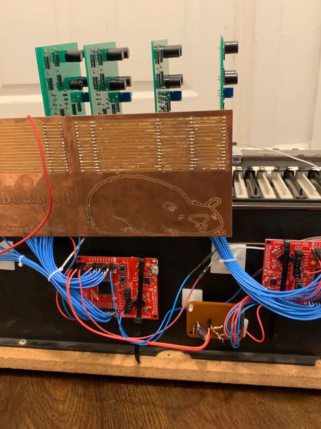
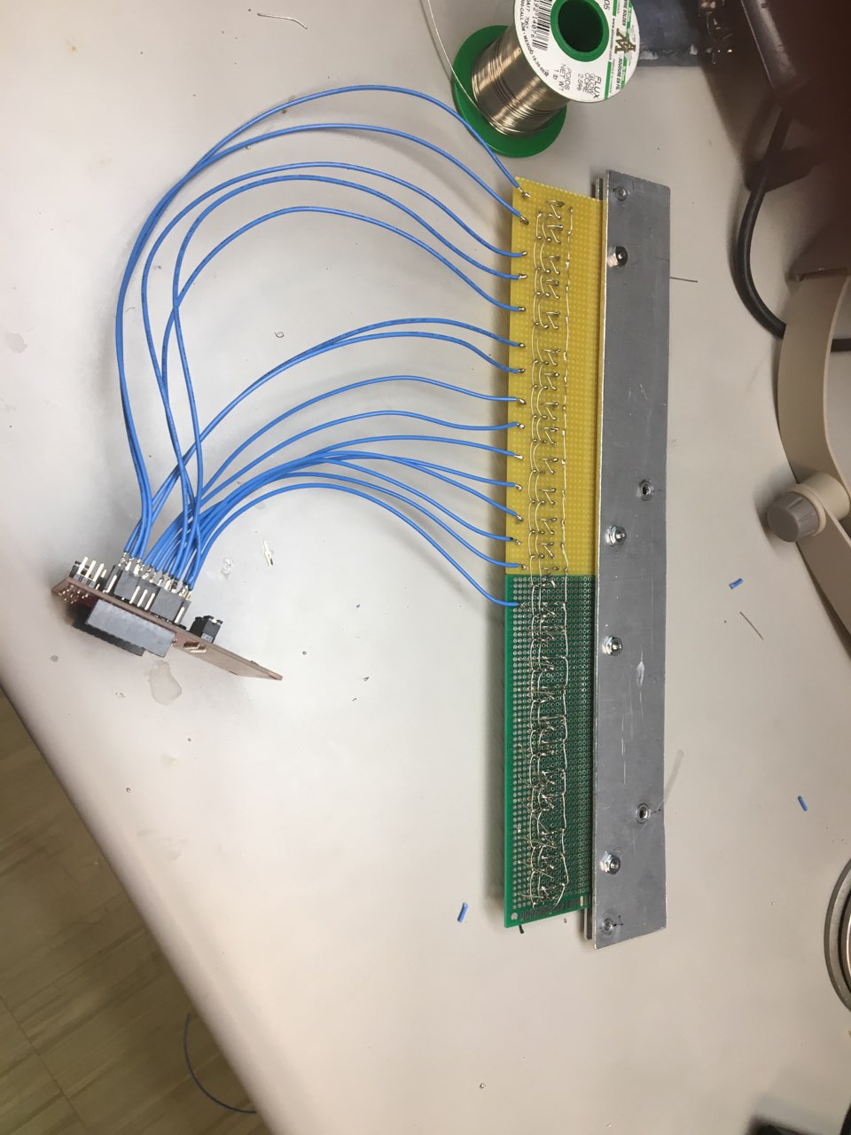
The Wombulator is a monophonic electronic bass synthesizer spanning a 2-octave range (A0–A2, 27.5–110 Hz). Built as the ECE Embedded Systems final project at Rowan University, it repurposes 25 keys from an antique Hammond Organ as the performance interface.

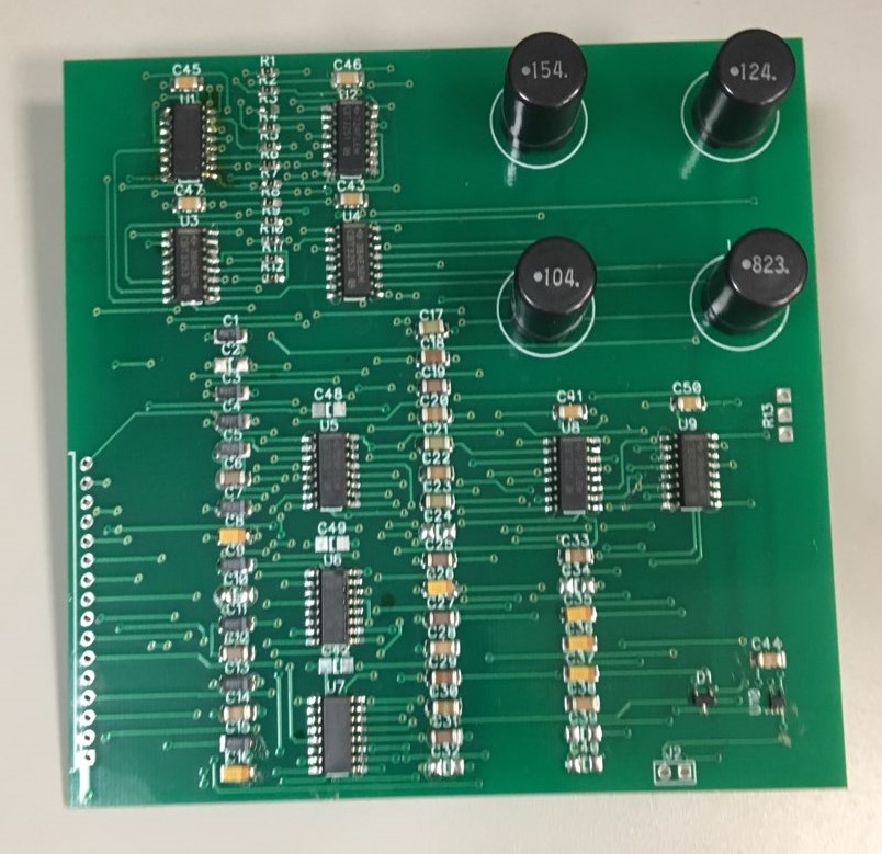
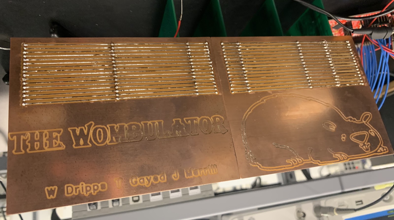
Two MSP430F5529 Launchpads communicate over UART: one reads the 25 hardware-debounced keys and transmits the active note; the other drives an 8-bit parallel DAC to generate a sawtooth waveform at the correct frequency, while switching analog multiplexers on four RLC notch filter boards. Switching boards in or out cuts different harmonics, changing the tone in real time.

The design was scoped for 8 filter boards, but four were completed within the project timeline.
Microcontrollers
2× MSP430F5529
DAC
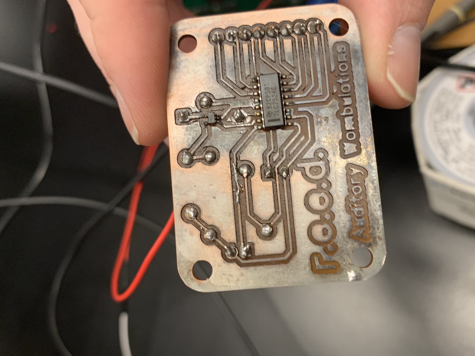
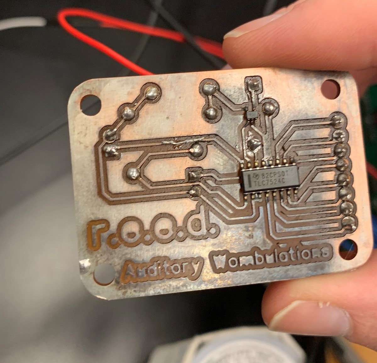
TLC7524CDR (8-bit)
Frequency Range
27.5 – 110 Hz
Keys
25 (A0 – A2)
Filter Boards
4 Switchable RLC Notch Filters
Waveform
Sawtooth (8-bit)
Inter-board Comms
UART @ 9600 baud
Debouncing
Hardware RC Network
Course
Embedded Systems · Final Project
Collaborators
Bill DrippsJames Merrill

Signal Chain

01

Key Input

25 snap-action switches (Hammond Organ keys) with RC hardware debouncing suppress contact bounce of 500–600 µs.

→
02

MSP430 #1 — Keyboard Reader

Polls 25 GPIO inputs. Priority encoder selects the highest active key. Transmits the note number over UART at 9600 baud.

→
03

MSP430 #2 — DAC Driver

Receives note via UART. Timer TB0 (SMCLK ~25 MHz) generates an 8-bit sawtooth ramp. Sets CCR0 per note for correct pitch. Drives 8-bit DAC and 14 multiplexer select lines.

→
04

TLC7524 DAC + Buffer

8-bit parallel DAC converts the digital ramp to an analog sawtooth. LMV321 op-amp in unity-gain buffers the output.

→
05

Switchable RLC Notch Filters × 4

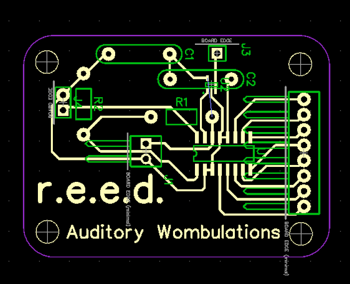
Four series RLC notch filter boards (Q ≈ 0.5). Switching boards in or out selects which harmonics are cut, shaping the tone; analog multiplexers retune R/L/C values for each of the 25 pitches.

→
06

Audio Output

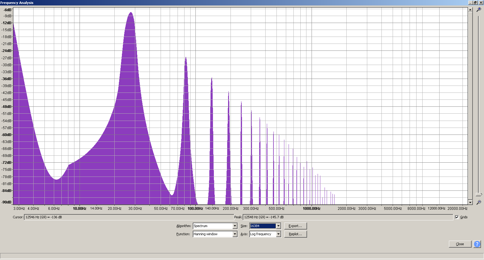
¼-inch output to amplifier. The sawtooth's harmonics are shaped by whichever filter boards are engaged, softening its tone toward a triangle-wave target.

System Block Diagram
Block diagram: keyboard switches feed MSP430 #1, which sends notes over UART to MSP430 #2; MSP430 #2 drives the DAC, whose sawtooth passes through the switchable RLC notch filters to the amplifier, while 14 filter-select lines from MSP430 #2 choose the filter settings. Keyboard Switches 25 Hammond keys · RC debounce MSP430F5529 #1 keyboard reader UART · 9600 baud MSP430F5529 #2 DAC driver · filter select TLC7524 8-bit DAC LMV321 unity-gain buffer sawtooth RLC Notch Filters × 4 switchable boards Amplifier ¼-inch output filter select · 14 lines

Engineering Breakdown

◈

Dual-MCU UART Architecture

Two MSP430F5529 boards communicate at 9600 baud over UART. Board 1 handles all 25 keyboard inputs; Board 2 drives the DAC and filter multiplexers in real time.

◈

Sawtooth Wave Generation

Timer TB0 runs from SMCLK raised to 25 MHz (the F5529's rated maximum) and triggers an ISR that increments an 8-bit counter. Modular arithmetic maps each bit to a DAC output pin, producing a binary ramp sawtooth.

◈

Hardware Switch Debouncing

Snap-action switches exhibit 500–600 µs of contact bounce. RC networks (~1 ms time constant) provide hardware debouncing, verified on oscilloscope before and after the filter stage.

◈

RLC Notch Filter Design

Series RLC notch filters with a damping ratio of ζ ≈ 1 (Q ≈ 0.5) give a broad cut rather than a narrow notch. Switching boards in or out selects which harmonics are attenuated; component values were calculated per note across all 25 pitches and populated on the PCBs.

◈

Analog Multiplexed Component Selection

14 GPIO select lines drive analog multiplexers (SN74CBT3251/3253) that switch pre-loaded R, L, and C combinations on each filter board to tune the notch frequency for every note.

◈

End-to-End System Integration

Covered keyboard interfacing, firmware, DAC circuit design, PCB layout, RLC filter theory, analog multiplexing, and final assembly — completing the full embedded systems design cycle.

Capabilities Used

// ELECTRICAL
Embedded Design PCB Design Fabrication Diagnosis
// HARDWARE
Analog Filters DAC / ADC Oscilloscope
// MECHANICAL
Machine Shop
// FIRMWARE
Embedded C PWM / Timers UART
Next project · 1 / 5 Self-Parking RC Car →